Case
Touch key OTP type microcontroller selection - padauk PMS1606.
PMS1606 touch key OTP type Padauk single-chip microcontroller, selection guide for PADAUK single-chip microcontroller, clock source with internal high-frequency RC oscillator (IHRC), internal low-frequency RC oscillator (ILRC)
◆ It is not recommended to be used in applications with AC resistance-capacitance step-down power supply or high EFT requirements.
◆ Operating temperature range: -20 °C ~ 70 °C.
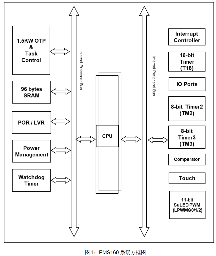
1.5KW OTP program memory.
96 bytes of data storage.
Up to 6 IO pins can be selected as touch keys.
One hardware 16-bit counter.
Two 8-bit hardware PWM generators Timer2/Timer3, which are also configured with NILRC oscillators whose frequency is slower than ILRC and is suitable for making a more power-saving wake-up clock.
A set of three-path 11-bit SuLED (Super LED) PWM generator and counter LPWMG0/LPWMG1/LPWMG2 that can be set.
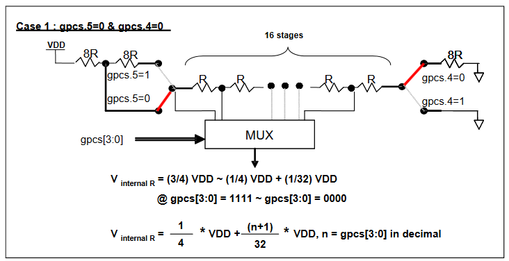
Provides a hardware comparator.
Six IO pins with pull-up/pull-down resistor options.
Bandgap circuit provides 1.2V Bandgap voltage.
Clock sources: internal high-frequency RC oscillator (IHRC), internal low-frequency RC oscillator (ILRC).
14 sections of LVR reset settings: 4.5V, 4.0V, 3.75V, 3.5V, 3.3V, 3.15V, 3.0V, 2.7V, 2.5V, 2.4V, 2.3V, 2.2V, 2.1V, 2.0V.
Two optional external interrupt pins.
Single processing unit operating mode.
Provides 82 valid instructions.
Most of them are 1T (single-cycle) instructions.
Programmable stack pointer and stack depth (using 2 bytes SRAM as a layer of the stack).
Data access supports direct and indirect addressing modes, and the data memory can be used as the data pointer (index pointer) of the indirect addressing mode.
IO address and storage address space are mutually independent.
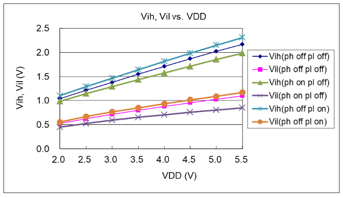
The maximum voltage must not exceed 5.5V, otherwise, the IC will be damaged.
Input voltage …………………………………… -0.3V to VDD + 0.3V
Operating temperature …………………………………… -20 °C to 70 °C
Storage temperature…………………………………… -50 °C to 125 °C
Junction temperature …………………………………… 150 °C
The back of the programmer, JP7 jumper.
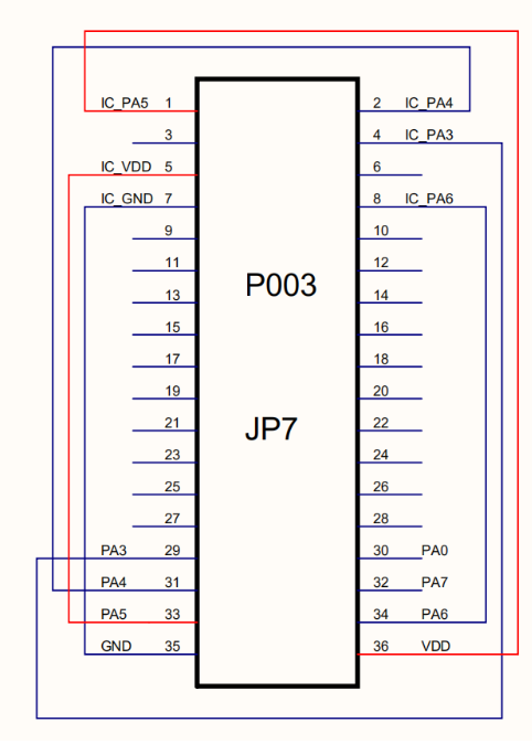
Please use the 5S-I-S01/2 (B) external touch panel 5S-I-TB002 (also known as PMS160_ICE_Touch kit) to simulate the PMS160. Refer to the following picture:
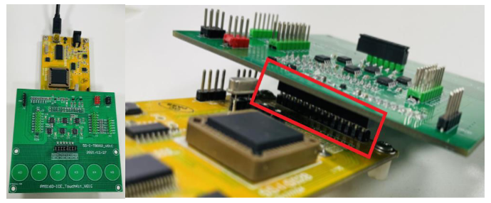
(1) Regarding simulation communication
This touch simulation board adopts the method of externally attaching the actual PMS160 IC for simulation, and the simulation of each functional module is more consistent with the actual IC. However, due to communication with the main simulator, the simulation speed will be slightly slowed down, so it is also not recommended to enter the interrupt too quickly and frequently (the frequency of entering the interrupt during simulation is recommended not to exceed 1 kHz). The actual IC is not limited by this.
Affected by the simulation communication, the oscillator module of IHRC/ILRC will always remain in the oscillating state. When setting to turn off IHRC/ILRC in the program, it will only be effective for the actual IC, so it is particularly necessary to pay attention to this difference when using IHRC/ILRC as the clock source for each Timer.
The simulation voltage range of this touch board is limited to 3.5V ~ 4.8V. If it is matched with the 5S-I-S01 standard simulator and the simulator uses the method of being powered by the external supply for simulation, the external power supply is not recommended to exceed 5V, otherwise, it may lead to unable to simulate or abnormal simulation results due to the voltage mismatch between the simulator and the touch board.
It does not support Timer3, LPWMG0/1/2 to select SYSCLK as the counter clock source.
It does not support Timer2 and Timer3 to select GPCRS as the counter clock source.
It does not support Timer2 to select NILRC as the counter clock source.
LPWMG2 and LPWMG0/1 belong to two different ICs for simulation, and the simulation frequency/phase will be slightly different, and it does not support the simulation of the LPWM function with complementary dead zones; when using the LPWM interrupt, the simulator will also add an extra Code Option: ICE_LPWM_INTR, for selecting the LPWMG interrupt source during simulation: from LPWMG0/1 or from LPWMG2.
When simulating the output of LPWM, the set output pin position will be forced to switch to the input state (forced to switch through the pac register, which does not affect the original setting value of registers such as padier and paph). After turning off the LPWM output, the input/output configuration of the corresponding port (pac register) needs to be switched by the user themselves. For the actual IC, this operation is not required.
During simulation, the wake-up time of the power saving/power off mode is not consistent with the actual IC, and it is related to the speed of the system clock frequency. Taking the system clock of 1 MHz as an example, the estimated wake-up time of stopexe in simulation is between 30 us and 1 ms; the wake-up of stopsys takes about 700 us. If there are related wake-up time requirements, it is recommended to use the actual IC to measure.
Considering the impact of simulation communication on IHRC/ILRC, in order to avoid the false wake-up of the Timer, it is recommended that customers turn off all the Timer modules that are not needed for wake-up before using stopexe/stopsys, rather than turning off the Timer clock source. Taking Timer2 as an example, the recommended programming approach is: "$ TM2C STOP".
Related News
Categories
News
Contact Us
Contact: Tianheng Technology
Phone: +8613265876004
Tel: +8675583041117
E-mail: jaycha5574842@qq.com
Add: Shenzhen City, Guangdong Province, China