Case
During the programming period, the PMS150G PADAUK single-chip microcontroller uses a lower voltage o
General OTP series
It is not recommended to be used in applications with AC resistance and capacitance step-down power supply or high EFT requirements
Operating temperature range: -40 °C ~ 85 °C
PMS150G 1KW 64 6
PMS150B 0.5KW 64 6
PMS150G is almost the same as PMS150C.

During programming, PMS150G uses a lower voltage on PA5, but uses a higher voltage than PMS150C on VCC.
When using the official Padauk programmer for programming, PMS150G requires a newer minimum hardware version (PDK5S-P003) than PMS150C (PDK3S-P002).
PMS150G can operate at 1.8V, while PMS150C requires at least 2.0V.
PMS150G requires more power when operating at a frequency of about 60 kHz (22 µA versus 13 µA).
Compared to PMS150C, PMS150G can drive and absorb more current on the I/O line.
PMS150G takes more time from power-on to start up.
The maximum clock of PMS150G is 2 MHz, while the maximum clock of PMS150C is 8 MHz.
1KW OTP program storage
64 Bytes of data storage
One 16-bit timer
One 8-bit timer (can be used as a PWM generator)
One general comparator
Each IO pin can be set with a wake-up function
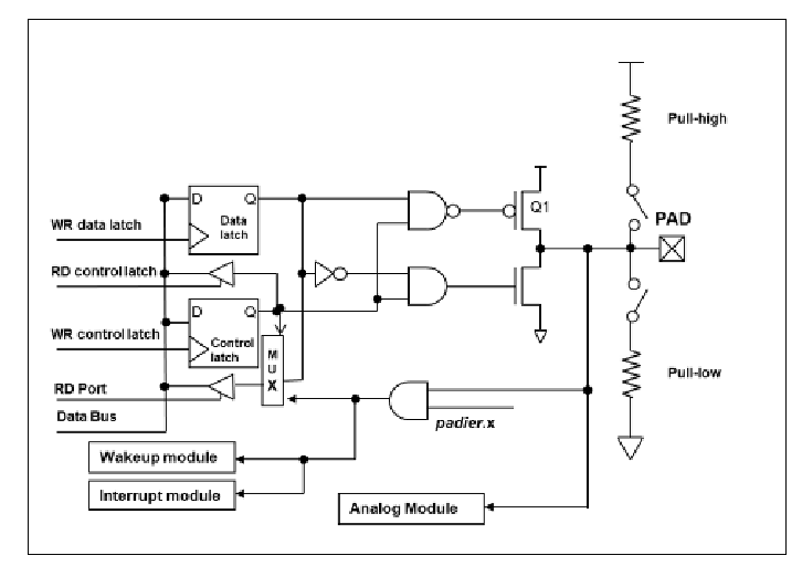
Six IO pins with input pull-up/pull-down resistors
Clock source: internal high-frequency oscillator, internal low-frequency oscillator
Eight-section LVR optional: 4.0V, 3.5V, 3.0V, 2.75V, 2.5V, 2.2V, 2.0V, 1.8V
One external interrupt pin
Single processing unit working mode
Provides 79 effective instructions
1T (single cycle) instruction
Programmable stack pointer and stack depth
Data access supports direct and indirect addressing modes, and the data memory can be used as the data pointer (index pointer) of the indirect addressing mode
Independent IO address and storage address space
PMS15B/PMS150G series 8-bit OTP IO type single-chip microcontroller read/write examples, since your PMS150G has additional factory value @0x3f5, you should exclude this term and change ==>.exclude_code_start = 0x3F5, then it should not complain about "non-blank" IC.
@0069 1000 // Add A, 0x00
@006a 1001 // Add A, 0x01
@006b 1002 // Add A, 0x02
@006c 1003 // Add A, 0x03
@006d 1004 // Add A, 0x04
@006e 1005 // Add A, 0x05
@006F 1006 // Add A, 0x06
@0070 1007 // Add A, 0x07
@0071 1008 // Add A, 0x08
@0072 1009 // Add A, 0x09
@0073 100a // Add A, 0x0A
@0074 100b // Add A, 0x0B
@0075 100c // Add A, 0x0C
@0076 100d // Add A, 0x0D
@0077 100e // Add A, 0x0E
@0078 100f // Add A, 0x0F
@0079 1010 // Add A, 0x10
@007A 1011 // Add A, 0x11
@007b 1012 // Add A, 0x12
@007c 1013 // Add A, 0x13
@007D 1014 // Add A, 0x14
@007e 1015 // Add A, 0x15
@007f 1016 // Add A, 0x16
@0080 1017 // Add A, 0x17
@0081 1018 // Add A, 0x18
@0082 1019 // Add A, 0x19
@0083 101a // ADD A, 0x1A
LA Check OTP at 150G at 0x080 for correct data "1017" Read data "1A42"........

.otpid = 0x2539,
.id12bit = 0x639,
.type = FPDK_IC_OTP1_2,
.addressbits = 12,
.codebits = 13,
.codewords = 0x400,
.ramsize = 0x40,
.exclude_code_start = 0x3F6,
.exclude_code_end = 0x400,
.vdd_cmd_read = 2.5,
.vpp_cmd_read = 5.5,
.vdd_read_hv = 2.5,
.vpp_read_hv = 5.5,
.vdd_cmd_write = 4.5,
.vpp_cmd_write = 8.0,
.vdd_write_hv = 6.5,
.vpp_write_hv = 8.0,
.write_block_size = 2,
.write_block_clock_groups = 1,
.write_block_clocks_per_group = 8,

Application scope: PMS150G
Preface
For the PMS150G chip when burning in the semi-automatic machine, its burning process may be interfered by the semi-automatic machine or other work noise, which in turn causes the burning yield to decrease, or even the IC to be burned out. This APN provides improvement countermeasures.
Description and improvement countermeasures
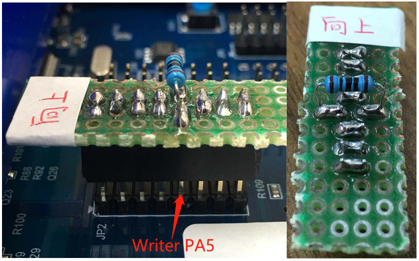
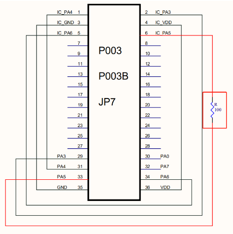
Taking PMS150G-S08 as an example, to improve the stability and reliability of IC batch burning, before burning, please string a 100Ω resistor on the PA5 pin of JP2 behind the Writer. The connection method refers to Figure 1:


Figure 2
Related News
Categories
News
Contact Us
Contact: Tianheng Technology
Phone: +8613265876004
Tel: +8675583041117
E-mail: jaycha5574842@qq.com
Add: Shenzhen City, Guangdong Province, China